Kenwood TM-271A Memory Scan Modification
The purpose of this modification is to provide remote control of the memory scan function of the Kenwood TM271A.  The Arcom controller is used to provide the necessary connections and functionality.

Background
As a avid remote base enthusiast, I often dial around the 2 meter band, one frequency at a time listening for signals of interest. Still, I've always thought that being able to put the radio into the memory scan mode would make the use of the TM271A much more dynamic and interesting. This mod allows the 271A to start and stop memory scan remotely as desired. All other functionality for the 271A remains intact.

For my repeater I had previously built a breakout box which allow for additional connections to the RC210. This provided space for the connections between the TM271A and the RC210, which includes a single reed relay connected to one of the controllers UF open collector outputs.

Parts Needed
About 32 inches of very small gauge stranded wire
About 48 inches of medium gauge stranded wire (e.g. #12)
An SPST 12 VDC reed relay
A small perf board for the reed relay
Two RCA phone jacks (female)
Two RCA phono plugs (male)
TM-271A Disassembly
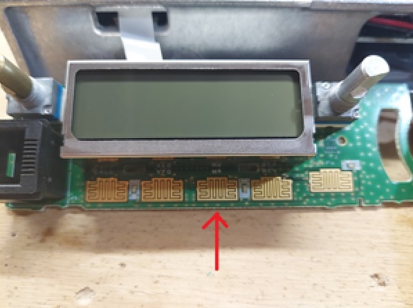
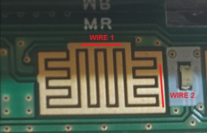
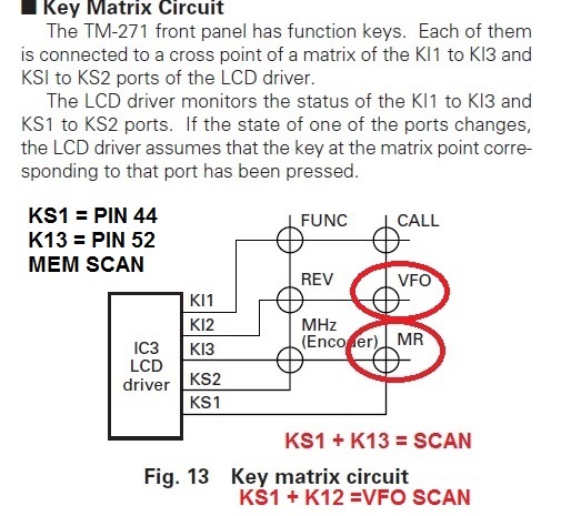
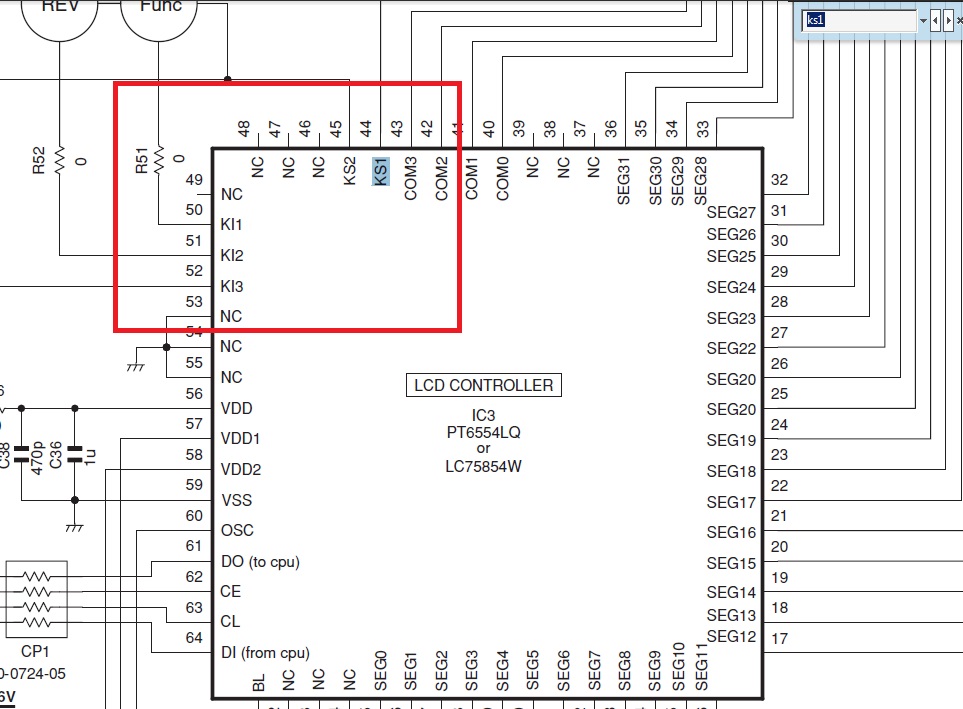
The CPU controls the scan function of the radio, using a matrix . The matrix determines which buttons on the front panel have been depressed and for how long. Access to the circuit traces is required which are located directly behind the "MR" button on the radio. This requires removing the display unit for the necessary connections.

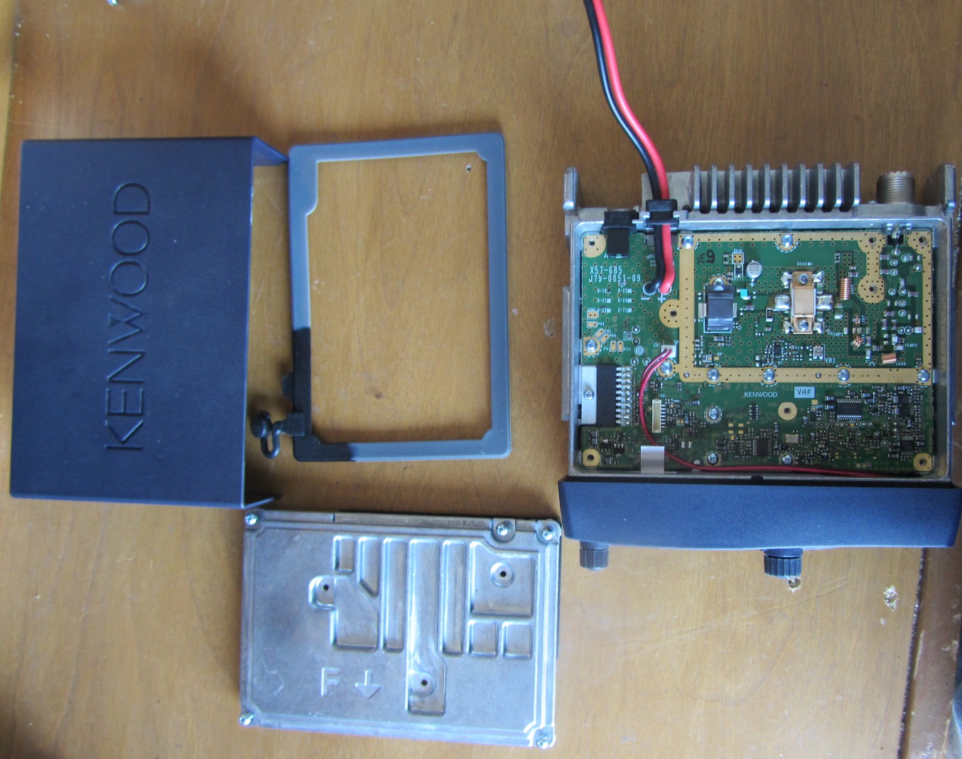
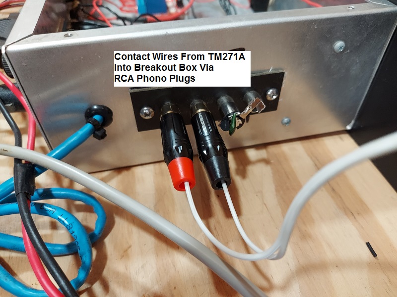
Disassembly of the radio is very easy. In addition to the display unit, the top cover and sub-cover need to be removed to route the two wires which will be soldered to the circuit traces.

Start by removing the top plastic cover. There are no screws, just gently pull the top off by pulling on either side out, and then lifting it away from the frame. Underneath is an aluminum cover, remove all of the screws from it and then gently pull the cover up to remove it, exposing the top circuit board. Now pull the two rubberized knobs off of the front of the radio.

To remove the display unit, turn the radio over and observe the small notches where the display unit joins with the main body of the radio. Using a flat head screwdriver, gently pop each of the two notches to release the display from the body of the radio.

When viewing the circuit board of the display unit, you will find two small black screws which secure the board to module. Remove the screws and gently pull the circuit board out of the display housing.
Solder Two Wires to the Display Unit Circuit Board
When looking at the front of the display unit, you will see the circuit pads that the buttons connect with. They are each labeled, such as Call, VFO and MR. Each pad has interlaced traces, two traces for each button. Two wires need to be soldered onto the MR trace as shown below.

Prior to soldering, prepare a pair of 16 inch long and small gauge wires by stripping 1/8 inch or less of the insulation away and tinning the wires with solder. If you use wires too large, it may impair the use of the front panel button. Route the wires from the top main body of the radio chassis then through either of the small holes in the back of the display unit. The result should be each of the wires being next to the MR pad prior to soldering.

This is an SMD board, so use much caution when soldering.  I used a small alligator clip to hold each wire in place to ease the job. Land each wire where shown in red as wire 1 and wire 2.
Initial Testing
After soldering the wires to the pad, power up the radio and test the connections by momentarily connecting the two wires together. A one second connection will start the memory scan and a brief tap together will stop the memory scan.

Wire Routing
The small wires used are not suitable for the external connection. Route the small wires through to the rear of the main chassis and solder to a larger wire pair for the external connection (a pair of wires long enough to connect to the RC210 or breakout box).  Use a small wire tie or two to make a strain relief inside and outside of the radio to ensure the wires are secure from being damaged by external forces.

Re-assemble the TM-271A
Reverse the steps from the disassembly to put the radio back together. Be sure the speaker is fully seated in the display unit. When reassembled, test to see if the MR button functions as it should.

Connection to the RC210
I soldered RCA phono plugs onto the ends of the two wires coming from the TM271A. Then, I added two phono jacks to a breakout box. Inside the breakout box I installed a small perf board with a reed relay. The relay has 12VDC provided to one side of the coil and one of the open collector outputs from the controller (UF1-8) provides the ground to actuate the reed relay upon command. There are lots of ways to configure these connections, this just happens to be the way I chose to do it.
Programming the Controller
To provide both the start and stop signal to the radio, we need a very brief connection (i.e. 100ms) and a one second or longer connection.  This is made very easy with the controller, especially if using RCP.  Make two macros, which will control the same logic output.

Macro 1 will turn on UF1, then have three "pause" commands (see the message vocabulary at the bottom of the list in RCP) from a message macro, and then turn off UF1. This provides the one-second long contact to start the memory scan.
Macro 2 will turn on UF1 and then turn off UF1. This provides the short momentary contact which will stop the memory scan.
References
Button Matrix
Circuit Diagram showing pads for KS1 (pin 44) and K13 (pin 52).